


Robotics Shop BD - one-stop shop for robotics, electronics, and PCB printing services in Bangladesh. Get best quality parts with warranty & expert tech support.
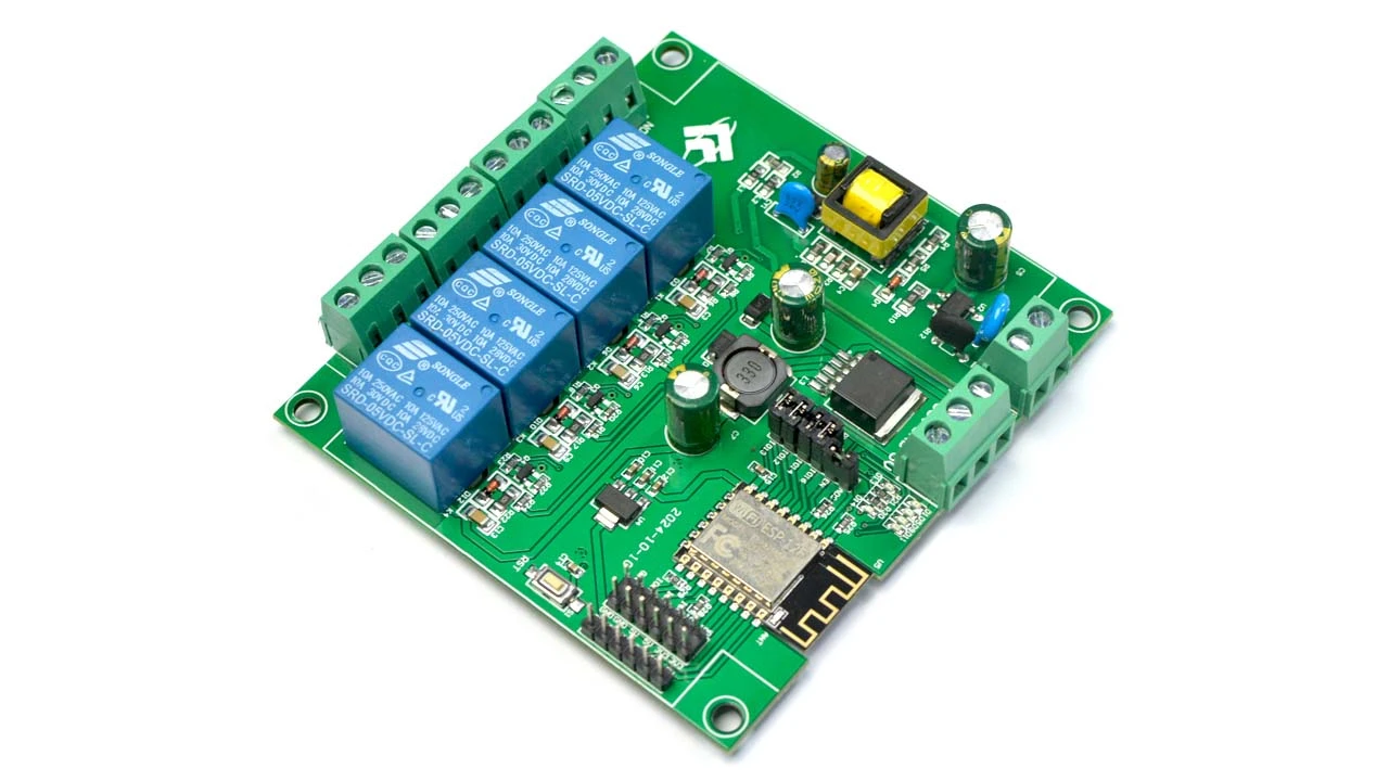
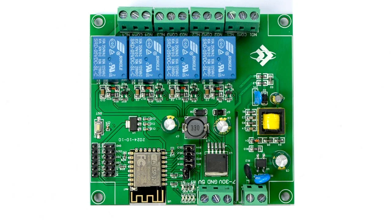
The ESP-12F WiFi 4-Channel Relay Module is a highly integrated solution for smart home automation and IoT applications. Built on the reliable ESP8266 ESP-12F WiFi module, this relay board enables wireless control of up to four AC or DC loads via mobile apps or microcontroller-based systems. Designed with a robust AC-DC power module and secondary development in mind, it supports Arduino IDE, ECLIPSE, and other development platforms.
Key Features
Built-in stable ESP-12F WiFi module with 4MB flash memory.
All GPIO and UART ports are broken out for easy secondary development.
Wide power input support: AC 90–250V / DC 7–30V / 5V.
Onboard reset button for the ESP module.
Compatible with Arduino IDE, ECLIPSE, and other development tools.
4-channel 5V relays support up to AC250V or DC30V switching.
Onboard power LED, programmable LED, and relay status indicators.
Technical Specifications:
Parameter
Specification
AC Power Supply
90–250V
DC Power Supply
7–30V or 5V
WiFi Module
Built-in ESP-12F with 4MB Flash Memory
I/O and UART Access
All ports are accessible via headers
Power Supply Module
Onboard AC-DC switching module
Development Support
Compatible with Arduino IDE
Relay Output
5V relays control AC/DC loads up to 10A
Indicators
Power LED, 1 programmable LED, relay indicators
Board Dimensions
93mm × 88mm
Interface Description
Programming Port:
Connect GND, RX, TX, and 5V of ESP8266 to external TTL serial port (GND to GND, TX to RX, RX to TX, 5V to 5V)
Connect IO0 to GND during programming, then disconnect after upload
Relay Output:
NC (Normally Closed): Connected to COM before relay activation
COM (Common): Relay common terminal
NO (Normally Open): Connected to COM after relay activation
GPIO Pinout:
All standard GPIOs of ESP8266 are accessible via headers for custom functionality or sensor integration
Program Download Guide
Connect IO0 to GND using jumper wires or caps
Use a TTL-to-USB adapter (e.g., FT232) and connect to PC
Connect to the board: GND↔GND, TX↔RX, RX↔TX, 5V↔5V
Select the correct COM port and board type in Arduino IDE
Click "Upload"; the code will compile and transfer to the board
After upload, disconnect IO0 from GND and reset the board
Applications
Smart home device control
Wireless industrial automation
IoT-based switching systems
Remote ON/OFF control
Security and access automation
Smart farming systems
Packaging Details
1 X ESP8266 ESP-12F 4 Channel Wifi IoT Smart Switch
Perfect for smart home, IoT devices, and automation systems. With wide voltage support, Arduino compatibility, and 4-channel control, it's a reliable and scalable choice for developers and enthusiasts in Bangladesh.